Also allowing the 470 being the backup frequency for the Sevier County Emergency Radio Service...
On with the news letter...
I have had two people ask me about coax and soldering, so hope that this will help..
Coax and Connectors
Back when I was pretty darn ignorant about coax and connectors, I thought in terms of two cable sizes - what I called thick and thin. The thick cable seemed to be about 1/2 inch in diameter, and carried lots of power. It was represented by products such as RG-8. The thin cable seemed to be about half of the diameter of the thick cable, carried far less power, and was represented by names such as RG-58 and RG-59. As they say, this is close, but no cigar. Here's a slightly more accurate view that will go a long way.
While there are many coax cables that are 1/2 inch in outside diameter, the true size of the cables that interface directly to PL-259 plugs is 0.405 inches. If you have a cable which is more than 0.405 inches in diameter, you can be pretty sure of a few things. First, it is probably a good quality/low loss cable. As a very general rule, subject to many factors, a larger cable has less loss (and usually a higher power rating). Second, you may have a difficult and/or expensive time getting connectors for the ends. While there are some very interesting techniques to adapt larger cables to PL-259 plugs, this page will not consider them. That's a whole world unto itself.
The standard PL-259 (also known as a UHF connector) is designed to directly accept 0.405 inch diameter cable. This includes popular cables such as RG-8, RG-213, and RG-11. While there are differences between different types and brands of PL-259 plugs, all will accept the 0.405 inch cable.
The so-called thin cables are a bit more complex to categorize. Most of the common cables fall into one of two diameters - either 0.195 or 0.24 inches. RG-58, for example has a diameter of 0.195 inches. RG-59 and RG-8X have a diameter of 0.24 inches.
There is only one PL-259 plug (in terms of size), regardless of the diameter of the cable. The thinner cables are installed with the aid of an adapter. The adapter screws into the PL-259 and provides a diameter reduction to the smaller size.
I know of two popular adapters, one for the 0.195 inch and the other for the 0.24 inch diameter cables. Perhaps there are more, since there are other thin cable diameters out there. But, for the vast majority of common thin cables, these two adapters will do the job. The adapter for the 0.195 inch cable is also known as the UG-175. The adapter for the 0.24 inch cable is the UG-176.
At the end of the day, for most amateur radio purposes, the parts needed for installing coax connectors include the PL-259 itself, and the UG-175 or UG-176 adapter, if you are going to be working with a thinner (0.195 or 0.24 inch) cable.
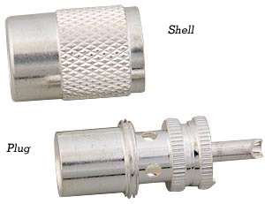
This page is really about installing PL-259's, not the connectors themselves. The catalog from The Wireman, Inc, called The Wirebook, contains a large amount of information about the different types of PL-259 plugs. The cost of a plug will depend upon the quality of the plug and the quantity purchased. Good quality plugs, purchased in quantity (10+), can cost around $1 (USD, 1998 timeframe) each at places such as hamfests. Purchased one at a time, from a specialty store, the cost might be as high as $4 per connector. I try to find quality plugs at hamfests and buy them in bulk. Usually, these are the silver-plated plugs with a Teflon center pin insulator. I have also ordered plugs and adapters over the Internet, and there are many good outlets.
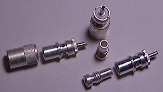 |
| PL-259 Plug and Adapter Examples |
One last point. I mentioned a few paragraphs back that all PL-259 connectors are the same size. This really isn't true, there will be some variations between brands and even from plug to plug from the same brand. I have not found that those small variations make a difference - with one exception. One of cables I have used is RF-9914F, BuryFlex (TM). This is a low-loss cable which can be directly buried in the ground, and bends into tight loops because the center conductor is stranded, not solid. It is a rugged cable available from the Radioware and Radio Bookstore. Its stranded center conductor is just ever so slightly larger than most all center pin holes. I find that approximately only one out of five different brands of PL-259 plugs will accept the conductor. With this exception, plugs may differ in quality, but they are otherwise interchangeable (in my experience).
The Process
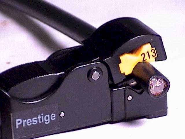
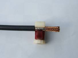
The process begins by cutting the cable to expose an end. The stripper is placed over the cable, with about an inch of cable between the stripper and the end. See the left picture below. You must put the stripper on the coax in the correct direction. That is, the blade settings determine which side of the stripper is nearest to the end. Be sure that this side is towards the cut end of the cable. Now comes a very important point. When rotating the stripper around the cable, be sure to rotate it in a clockwise direction, when looking at the cable from the exposed end. This is important for several reasons. First, this direction causes the blades to cut from back to front. This tends to keep the cable within the stripper. If you rotate in the other direction, there is a greater tendency for the cable to want to walk out of the stripper jaws. This is especially true as the blades become more and more dull, and cut with more and more friction. The second reason is that this clockwise direction is the same direction that will be used to install the PL-259 when it is screwed onto the end of the cable.
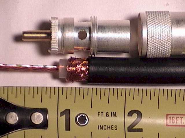
In the ideal world, the braid would be cut cleanly without being moved. The truth is, however, that the act of running the stripper around the cable causes the braid to twist around the center insulator as well as be cut. You want this twist to be in the same direction as the PL-259 threads. If you run the stripper in the other direction, the braid will want to untwist when you are screwing on the PL-259, and this just makes an unnecessary problem. If you look closely at the middle picture below, you can see how the very end of the braid is twisted to run around the center insulator. This is just an unavoidable side-effect of the process of turning the stripper around the coax. It really is not an issue, unless you go in the wrong direction.
Knowing how many times to rotate the stripper is also an art. It is possible to rotate it too few, or too many times. My own experience is that I turn it so long as I can hear the sound of the braid being cut. Yes, this is a very distinctive sound. It usually takes about 5 to 8 turns. A three blade stripper will take more turns than a two blade stripper. Let's remember what's going on here. A set of blades are pressing against a cable by the force of a spring. As the stripper rotates, the blades start to penetrate into the cable. All of the blades need to cut through the one or more layers of different material types. If you do not turn the stripper enough, you will not make a deep enough cut. If you turn it too many times, you may cut deeper than you want. If you consistently are cutting too deep on all of the blades, then you have to readjust the stripper to lower all of the blades together. I mean lower the blades in the stripper so that they penetrate less into the cable.
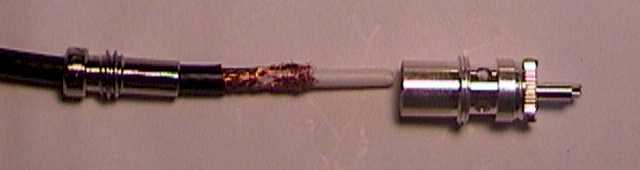
 |  |  |
| Positioning the Stripper | Stripped and Ready | Gripped and Ready |
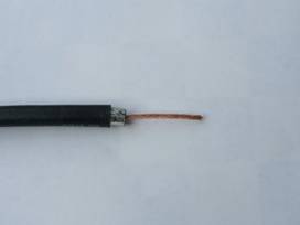
The middle picture shows the end of the cable after being stripped. It took only a few seconds to go from the left picture to the middle picture. The stripper does a great job, very quickly. If you use a stripper to prepare the cable, the blade to blade side spacing, which is not adjustable, will determine the length of each exposed section. As you can see in the middle picture, the length of the center insulator from it's end to the start of the braid is approximately 1/8 of an inch. The exposed braid section is approximately 5/16 of an inch. These dimensions match the typical instructions given in sources such as the ARRL Handbook. The center conductor can be any length, so long as it is longer than the PL-259 center pin barrel.
The middle picture also shows the prepared coax next to a PL-259 plug. The center conductor is more than long enough to extend out of the end of the center pin barrel. The center insulator can seat right against the insulator in the plug. The exposed braid is held back from the end (to discourage electrical shorting), but is yet visible through the holes in the barrel of the plug. Finally, the coax jacket can fully thread into the plug, providing a strong grip on the cable, as well as moisture protection.
The next step is to screw the PL-259 onto the cable. Prior to this step, be sure that all of the fine braid wires are not touching the center conductor. This may sound rather obvious, but some of the braid wires are very fine, almost to the point of hair. All it takes to cause trouble is one stray braid wire, that is not dressed with all of the rest, shorting out to the center conductor. Screwing the PL-259 onto the cable can take some muscle. Usually, the problem is that it's hard to grip the small connector and turn it onto the cable. Here's where I start to employ the vise grips. I use my larger pair to grab the connector and use it as a big level arm to aid in screwing the connector onto the cable. Do not put too much force on the PL-259. They are relatively fragile, and I have no doubt that overly aggressive vise grips could bend them out of round, which would cause no end of trouble. Since the PL-259 and the vise grips are both usually knurled, you can make a firm grip with very little pressure. Show your manliness in other ways.
Oh, by the way - before you screw on the PL-259, please make sure that you first put the outer sleeve onto the cable. I think that everybody has, sooner or later, attached a connector then discovered that the outer sleeve is sitting on the desk. This leads to both a laugh and a tear, and is not a suggested step. Be sure that the outer sleeve is put on in the correct direction. That little variation seems to provide less laughter, and far more tears.
Next, be sure that the PL-259 is completely seated on the cable. As you get closer to this goal, you will see the center insulator then the braid go past the solder holes in the barrel. You should be able to tell that the connector is completely seated by a change in the turning resistance - it should become impossible to screw the connector on any further. Again, this is a step that should be done with moderation. If you tighten the PL-259 too much on the cable you could short out the cable, or, strip the threads formed (cut) in the coax jacket.
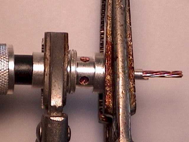
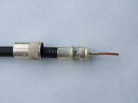
The right picture above shows the cable, with a PL-259 screwed onto its end. The outer sleeve is also already on the cable, and even faces the right direction. Here's where I use the pair of vise grips to grab the connector on each side of the solder holes. This arrangement holds the cable in a horizontal position, which is a convenient place for soldering. It also provides a good heat sink in the critical areas of the cable jacket and the center pin insulator. Neither vise grip is too tight. They grab the connector only enough to hold it, not enough to deform it.
Now when I grip the PL-259, I orient it so that two of the four solder holes are facing up. At this point, all we have to do is to solder the center pin, then the four holes in the barrel, and we are done. I do this in two steps. In the first step, I solder the center pin, then the two barrel holes that are facing up. After the end cools down, and I let it cool for several minutes so that I don't risk creating a cold-solder joint, I rotate the cable 180 degrees so that I can solder the last two barrel holes.
Before I solder, however, I use my Ohm meter to verify that the cable is not shorted. If you read a short (0 Ohms), it might not be your connector installation job. It may be true that the opposite end of the cable is providing the short. I have seen cases where the opposite end of the cable has a rough cut - so rough that the braid touches the center conductor. But if you do find a short in your connector, you still can take the end apart and fix it before applying solder. Personally, once I put a plug on the end of the cable, I don't try to fix the end if there is a problem. I just remove the plug, recut the end, and start over with the coax stripper. Another situation which may come up is that the opposite end of the cable is shunted by an inductor. This could happen if the cable directly connects to the base of a mobile antenna, where the inductor is part of an impedance matching network. In that case, the cable will appear shorted for direct current (DC), even though nothing is wrong. Don't falsely blame your connector when the issue is at the other end of the cable. Assuming that the opposite end of the cable is open, the connector end should measure an infinite impedance.
Once I determine that the cable is not shorted, I solder the center pin. I apply the torch flame to the end of the barrel, where I can heat up both the barrel and the center conductor. The usual rule here is to heat the work, not the solder. After perhaps 5 seconds, I can touch the solder to the end of the barrel and it will flow. I try not to get solder on the outside of the barrel. Usually, there is such strong capillary action that touching the solder to the center conductor near the end of the barrel will cause the solder to flow up into the barrel. Don't apply too much solder. In the extreme, it will flow up the entire length of the barrel and possibly short out the braid. Certainly apply enough solder so that the end of the barrel is sealed.
After soldering the center conductor, I again check with the Ohm meter, and make sure that the connector is not shorted. Once the center pin is cool, the excess center conductor can be trimmer off with a sharp diagonal pliers.
My next step is to use the torch to heat the PL-259 barrel right between the top two holes. This should be the top of the barrel, if you oriented it as I suggested. After perhaps 10 seconds, the solder will flow into both top holes. The goal here is make sure that there is enough heat and solder to make a strong connection, that the holes are completely filled with solder (no visible braid), but that there is not so much heat and solder that the center insulator melts, potentially shorting the cable. Another potential problem with using too much solder is that it flows into the threads on the barrel, or that it hangs down from the barrel in a big blob. Both of these situations should be avoided.
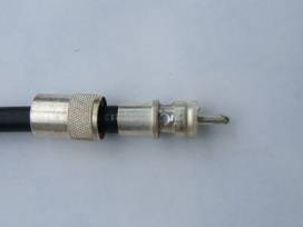
After the connector cools down, I again use the Ohm meter to check that the cable is not shorted. Here is a picture of the connector after soldering the center conductor, and the top two holes.
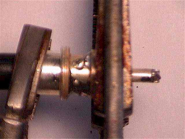 |
| Soldered Center Conductor and Top Two Holes |
The holes have been completely filled with solder, providing protection against moisture getting into the end of the cable. When the cable is cool, I release the vise grips and rotate the cable 180 degrees so that the remaining two holes are pointing up. Those hole are soldered, and a final Ohm meter check guarantees that the cable is not shorted. Even with the vise grips acting as heat sinks, the connector will remain quite hot for several minutes. Please don't burn your fingers grabbing a hot plug.
Some installation procedures suggest tinning the braid and/or center conductor before installation. I do not do that step. I find that I have no problems making strong solder joints, and tinning can cause big trouble if it adds enough solder so that the center conductor no longer fits into the barrel, or if the braid no longer fits within the PL-259 body. I do not aim the torch directly at a hole, but between the holes. The only purpose of the holes (in my approach) is to provide a place to introduce the solder. If you are using sufficient heat, capillary action will suck the solder into the hole, and into the region between the holes. The goal is to have the braid soldered to the plug around the entire circumference of the coax. It is not just 4 dots of solder in the holes. Tinning the entire braid will improve the chances of accomplishing this. Whatever you do, aim for a soldered connection around the entire braid, not just dots at the holes.
In recent (November, 2001) issues of QST magazine, I've noticed that Cable X-Perts installs a piece of heat-shrink tubing over the back end of their ready-made coaxial cable assemblies. This would provide additional protection against moisture infiltration through the back of the connector. While I have never seen the need for this added protection, it certainly can't hurt.
Adapters
When using an adapter, the procedure is very similar. During the preparation phase, it is necessary to expose more braid. This braid is folded back on the adapter before the adapter is screwed into the PL-259.
 | 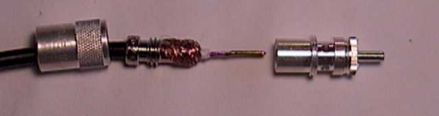 | 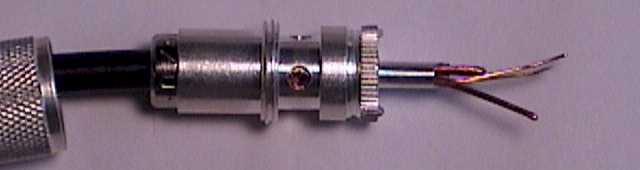 |
| Thin Coax with Adapter | Braid folded back on the Adapter | Adapter installed in PL-259 |
The left picture shows the adapter on the coax. The exposed braid has been extended to provide enough length so that when it is folded back onto the adapter, the braid covers the adapter all the way down to the threads. Do not let the braid slop over the threads, however, since it will be impossible to screw the adapter into the PL-259 if there is any braid on the threads.
The middle picture shows the braid folded back on the adapter. In addition, the center conductor has been stripped back, with a small amount of center insulator separating the braid from the center conductor.
The right picture shows the adapter installed in the PL-259, before soldering. The braid is visible through the holes in the PL-259 body. If you examine the end of the center pin barrel, you will notice that I've taken some folded over solid wire and inserted it into the barrel, next to the center conductor. In some cases, the center wire of the thinner coax is so much smaller than the center pin barrel that the only material connecting the two might be the solder itself. This is an undesirable condition, as solder is really meant to provide mechanical support, not an electrical connection. So, the hookup wire helps fill the large volume of the pin, and insures a positive metal to metal contact between the center conductor and the barrel. When the barrel is properly heated, the solder will flow into the barrel, and create a closed and mechanically rigid space.
At this point in the process the adapter installation merges with the normal installation, which is to say that you have to solder the center pin, then the four holes, and then you are done.
From HCARC..
Soldering PL-259 Coax Connectors
Introduction:
My first experience with the PL-259 coaxial connecter came into my life when I was in my teens. Like so many others, my two way radio experience was generated through contact with the use of "Citizens Band" radio back in the early 60's. I remember soldering PL-259 connectors onto RG-8U type coax but for some reason they never quite turned out looking like the pictures shown in the instruction manuals. Then one day while I was visiting a friend and HAM at the Navy's instrument calibration lab in Trenton, NJ, I noticed he was assembling PL-259 connectors onto RG-213U cable. I was amazed at how precise he was in his installation and how he made up these cables with ease. As we talked he reveled how at one point in his life with the US Air Force he sat in a small shack at the end of a runway making up coaxial cables for radio navigational systems. He also instructed me in the method he used which I will relay to you here. Over the years I've read all the pro's and con's of several methods and how the "Amphenol" method is the only correct way to install the PL-259 connectors. I've also been told that using a soldering gun instead of an iron is taboo. All I can say is that this is the method I use and I'm going to let you decide on the best method you want to use.
Tools that I use:
· Utility knife
· 1/4 " square, triangular or flat file (without handle)
· Small tubing cutter (nylon preferred)
· Common pliers
· Wire cutters
· Soldering rosin (liquid preferred)
· Weller 240/260 watt soldering gun (or suitable iron)
· A good quality 60/40 solder
· Volt-ohm meter
· Petroleum jelly ell or other light lubricant
· Denatured alcohol (rubbing alcohol)
· Paper towel or rag
A word about connectors:
There are a lot of connectors on the market. Some connectors are very well made and some are pure junk. I prefer to use connectors that don't have a bright shiny finished on them however a Nichol plated shell is fine. These tend to be much more difficult to solder to.
A word about coax cable:
The method described here is intended to be used with RG-8, RG-213 type coax constructed with a solid insulator. It is not recommended to be used with coax constructed with foam type insulation. While there are many coax cables that are 1/2 inch in outside diameter, the true size of the cables that interface directly to PL-259 plugs is 0.405 inches. These instructions will not cover the use of reducers required for adapting the PL-259 to be used with coax such as RG-8X, RG-58 or RG-59.
The Process:
- Start with preparing the PL-259.
- Remove the shell from the plug and set aside.
- Using the handle end of the file insert the tip into each solder hole on the plug and scrape the edge to remove any debris or plating. You should see bare brass.
- Next lay the file flat into the area with the holes and lightly remove any burs created from cleaning out the holes. At this time you may want to remove the plating finish around the holes exposing the brass material.
- Next let's move to the coax and prepare it for accepting the connector.
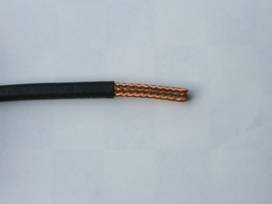
- Remove about 2 inches of the coax outer covering known as the jacket. Do this with a sharp utility knife making sure not to nick the wire braid below it. The best method I've found using a utility knife is to score the jacket then bend the coax slightly. This will allow the scored area to split lessening the chances of nicking the braid below it. This may take a little patience at first but with practice it will become easier. If you nick the braid, cut off the coax and start over. Remember, RF travels on the outside of this braid too. By the way, there are special coax cutters manufactured specifically for this purpose but they are in the $50 to $100 price range. The choice is yours.
- Apply one or two drops of rosin on the newly exposed braid close to the jacket. Use the rosin sparingly and don't over do it. A little goes a long way. The purpose of this step is to allow the solder used in the next step to flow quickly lessening the heat exposure time when applying the solder.
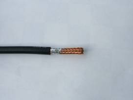
- Using your soldering gun or iron, apply just enough solder to wick onto the braid from the jacket toward the end of the coax covering about ½ to ¾ inch all the way around the diameter of the braid.
- Let the solder and coax cool.
- Using the tubing cutter, position the outer edge of the tubing cutter housing against the end of the coax jacket. This should position the cutting wheel of the tubing cutter the proper distance away from the end of the coax jacket allowing just enough tinned braid to remain after cutting. Continue adjusting the cutter deeper as you rotate the cutter. This will cut through the coax braid and dielectric material. Continue until you have run out of adjustment with the tubing cutter wheel.
- Remove the tubing cutter from the coax. You will notice that the cutting wheel will most likely not reach the center conductor of the coax.
- Take the utility knife and gently cut into the cut the tubing cutter made. Cut into the dielectric carefully making sure you do not nick the center conductor. If you nick the center conductor, cut off your work and start over.
- Once you have cut close to the center conductor you can pull on the scrap end of the coax removing the excess braid, dielectric material exposing the center conductor. This may have to be accomplished with some force or the use of pliers on the scrap end. A slight twisting motion in the natural twist of the center conductor while removing the scrap may also help.
- Now you should have the coax with about 3/8" tinned section exposed along with about 1 ½" of exposed center conductor. You are now ready to install the PL-259 connector.
- Place the shell of the connector on the coax in the proper direction. (The threaded end facing the end of the coax you just prepared). DO NOT FORGET THIS STEP…!!!
- Apply a very small amount of lubricant on the jacket. (cover about ¼ inch in length and all the way around the end of the jacket) This will help lubricate the plug as it screws over the jacket in the next step.
- Place the plug of the PL-259 on the end of the coax and screw the plug on until it bottoms onto the coax. At this point you may want to back the plug off the coax about 1/8 turn. This will give the coax a little gap between the dielectric and the insulator inside the plug.
- Looking through the holes in the connector plug you should see the tinned braid. Apply enough solder into each hole to ensure a good electrical connection. Don't get carried away with the heat from the soldering gun or iron. Also ensure that all holes are completely sealed with solder to help prevent water from getting into the holes.
- At this point you may want to lightly try to turn the plug on the coax. If the plug turns it hasn't been soldered properly and additional solder needs to be added to each hole.
- Next check for continuity (a short) between the coax center conductor that should be protruding out of the connector pin and the body of the connector plug. You are checking for no continuity (an open) between these two points. I've deliberately not soldered the center pin prior to making this first check. This is so it will be easier to remove the connector if you find a short at this time.
- Next check for continuity between the body of the plug and the shield at the opposite end of the coax if possible. You should have a good electrical connection.
- If all is well, than solder the center connecter pin to the center conductor of the coax.
- Clip off the excess center conductor at the tip of the connector pin and ensure you have a good solder connection. Add a little more solder to the tip.
- Check for a short between the center pin and the body of the plug of the connector. If there is continuity at these two points then you have a shorted plug and you will have to start over. If you wait to make these checks after you have installed both connectors, you will not know which end has the bad connection. You will have a 50/50 chance of being correct in your guess as to which one is bad so test each connector as you install them.
- After all the connectors have been installed and checked for proper continuity, clean off the excess rosin with the alcohol and screw the shells onto the connector plugs.
Remove about 2" of the jacket. Tin about ¾" close to the jacket.
Place the tubing cutter against the jacket. Cut into the tinned braid/dielectric and
remove.
Install the shell then screw the plug on and After checking continuity and plug security;
solder the plug. cut off excess center conductor and cut the tip.
Well these are two great articles, practice makes perfect, I use to really screw them up but being in the business to have to solder ends on I did get pretty good..hope you enjoy and good soldering !!
**********************************************************************************************************************************************
Here is a good article on the UHF Connector...
http://en.wikipedia.org/wiki/UHF_connector***************************************************************************************
Chip Implants !
Real or Fiction, Do we know the real story ?
" . . . and cause that as many as would not worship the image of the beast should be killed. And he causeth all, both small and great, rich and poor, free and bond, to receive a mark in their right hand, or in their foreheads: and that no man might buy or sell, save he that had the mark, or the name of the beast, or the number of his name."
-- Revelation 13:15-17
http://www.greaterthings.com/News/Chip_Implants/index.html#Microchips
&
http://www.antichips.com/
&
http://noverichipinside.com/
note the above link has several categories about chip implants !!
Worth reading more on this, our animals already have them in most, and some humans have, many pages of information , can be found on the internet, just look and research .....
*****************************************************************************************************************************************************
White House Names Ham as New Cybersecurity Coordinator

President Barack Obama greets his new White House Cyber Security Chief Howard A. Schmidt in the Cross Hall of the White House. December 17, 2009. [Lawrence Jackson, official White House photo]
On Tuesday, December 22, President Barack Obama named Howard A. Schmidt, W7HAS, as the new White House Cybersecurity Coordinator. According to the White House, Schmidt -- an ARRL member -- is one of the world's leading authorities on computer security, with some 40 years of experience in government, business and law enforcement and "will have regular access to the President and serve as a key member of his National Security Staff. He will also work closely with his economic team to ensure that our cybersecurity efforts keep the Nation secure and prosperous."
In a 2003 interview with The New Atlantis, Schmidt described cybersecurity as "the realization that computer systems affect our basic needs on a daily basis. Electricity, water, telephone -- these things are all run by computers, and my job is to work with owners and operators and government agencies to make sure that they continue to function properly and are not disrupted because of security events that then, in turn, affect our daily lives."
Schmidt told the ARRL that he credits Amateur Radio with getting him involved with technology: "In high school, one of my friends was a ham and he got me interested in shortwave radio, which in turn got me into building shortwave radios and equipment, many from Heathkit. As I got older, I took courses from NRI and Bell and Howell in electronics and built a number of projects, preparing me for my first ham radio ticket. I love technology, and it was Amateur Radio that caused me to build my first computer -- a Sinclair ZX-80 to use for EME calculations. I studied all about the OSCAR systems and would build equipment to monitor when they would pass within range of Arizona. Building these computers to support my ham radio hobby gave me the technical skills that I need to not only start doing computer crime investigations and work on the early stages of computer forensics, in turn enabling me to start working on cybersecurity issues."
Schmidt is no stranger to the White House -- he served as a cyber-adviser in President George W. Bush's White House. After the 9/11 attacks, President Bush appointed Schmidt as the Vice Chairman of the President's Critical Infrastructure Protection Board and as the Special Adviser for Cyberspace Security for the White House. While at the White House, he assisted in the creation of the US National Strategy to Secure Cyberspace, becoming Chairman in January 2003. In May 2003, Schmidt retired from the White House after 31 years of public service in local and federal government.
Schmidt as a Ham
Schmidt has been an Amateur Radio operator for more than 30 years. "I was first licensed in the late 1970s as a Technician class licensee with the call sign WB7NUV," he told the ARRL. "I did a lot on 2 meters, 70 cm and on Packet. The TAPR group out of Tucson was real inspiration to me as I found the work they were doing absolutely wonderful. I started as a part of the Arizona Repeater Association (ARA) and lived for our annual hamfest at Ft Tuthill in Flagstaff."
Back in the 1980s, Schmidt told the ARRL that he tried moonbounce and had "a full shack of RTTY machines -- Teletype Corporation models 15 and 19 and even a model 21. I would spend weekends printing reams of pictures from Ricky, W0CKY, and all of the great TTY pictures he would transmit. I still have my Collins KWM 2A, 312B station console and accessories. While I have not used it for years, it is one of my treasured possessions. Through the years, I had about every type of HF radio made and even have my Collins R-388 and R-390 in a 19 inch rack. I will never forget the day we were able to talk to Southern California on a 2 meter handheld with the repeaters we had from Central Ariz. During the '100 year flood' in Arizona, the community of Rainbow Valley was essentially cut off from the rest of the state to the north when a bridge and power lines were washed away. Using ham radio equipment, we were able to coordinate moving in food, water, medical supplies and generators from the Air Force base I was working at (then Gila Bend Air Force Auxiliary Field) and work with the county sheriff's office to coordinate support."
Schmidt said that as with many other things, his love for Amateur Radio took a back seat to work, family and life in general: "While I got rid of all of my RTTY equipment back in the early 90's, I have continued to follow all of the great advances of ham radio." He said that only just recently, he got back into the hobby after what he called "an administrative error."
"Someone with a call very similar to mine upgraded to Extra class and when the form was sent to FCC, they mistyped one letter and it was my call that was submitted," he explained. "You can imagine my surprise when I received my Extra class license and new call in the mail. When I tried to find out what happened I was told (wrongly) that I was probably 'grandfathered.' I went out and bought an all band/all mode rig, antennas, power supplies, batteries -- everything I needed to outfit my shack. When all was said and done, we got the error fixed, but by that time, I was hooked on Amateur Radio all over again. I am now in the process of doing a room addition to be my new ham shack! I rejoined ARRL and now have room full of new gear waiting for the remodel to be done. Thanks to what I learned from the many hams on Web sites, I even built in PVC pipes through the walls to run my antennas."
Schmidt's Rise to Cybersecurity Czar
Schmidt began his government service in 1967 -- starting with a tour in the US Air Force -- both in active duty and in the civil service. After leaving the Air Force in 1983, he joined the Chandler (Arizona) Police Department, serving on the SWAT team and the Organized Crime and Drug Enforcement Unit; he formed and led the Special Enforcement Team. In 11 years as a local first responder he dealt with numerous issues surrounding emergency response to local incidents. While on the police force, he was instrumental in selecting, designing and the operation of interoperable communications and a public safety response system. Schmidt left the police department in 1994 to join the FBI at the National Drug Intelligence Center to head up the Computer Exploitation Team.
Schmidt went on to become a Supervisory Special Agent and Director of the Air Force Office of Special Investigations' (AFOSI) Computer Forensics Lab and Computer Crime and Information Warfare Division. In 1996, while serving in that position, he established the first dedicated computer forensics lab in the government, which was the basis for the formation of the Defense Computer Forensic Laboratory (DCFL). In 1997, Schmidt joined Microsoft as the Director of Information Security, Chief Information Security Officer (CISO) and Chief Security Officer (CSO), leaving in 2001 to join the White House. When he retired from government service in May 2003, he joined the online auction site eBay as their Vice President and Chief Information Security Officer and Chief Security Strategist.
Throughout his industry career, Schmidt has served as a reservist in the National Guard and Army. He served in the Arizona Air National Guard as computer communications specialist from 1989-1998, then transferred to the US Army Reserves as a Special Agent in the Criminal Investigation Division where he continues to serve with the Computer Crime Investigations Unit at CID HQ. He has testified as an expert witness in federal and military courts in the areas of computer crime, computer forensics and Internet crime.
After Schmidt retired from eBay, he started his own consulting firm, R&H Security Consulting. In September 2008, he took over as President and CEO of Information Security Forum Ltd; he remains CEO until he begins his White House appointment in January 2010. He is also a board member of the Finnish security company Codenomicon, International President of the Information Systems Security Association and board member of the International Information Systems Security Certification Consortium, commonly known as (ISC). In October 2008, he was named one of the 50 most influential people in business IT by the readers and editors of Baseline Magazine.
Schmidt serves on the Executive Committee of the Information Technology Sector Coordination Council. He is a member of the High Technology Crime Investigation Association, the American Academy of Forensic Sciences and the International Association of Chiefs of Police. He has testified before congressional committees on computer security and cyber crime and has been featured on BBC, ABC, CNN, CNBC and Fox TV discussing cybersecurity, investigations and technology. He is the author of Patrolling Cyberspace, Lessons Learned from a Lifetime in Data Security and a contributor to The Black Book on Corporate Security.
Now that Schmidt has rediscovered how much fun Amateur Radio can be, he has no plans to let his enjoyment pass him by again. "I have my multi-band handheld transceiver next to my suitcase to take back to DC with me," he told the ARRL. "I hope to set up a station once I get settled. I do not plan on letting any more years slip by and not enjoying this great hobby."
*********************************************************************************************************************************
No Tuner Antenna
http://www.antennex.com/preview/notuner.htmFrom W8WWV.. Antenna Page..
http://www.seed-solutions.com/gregordy/Amateur%20Radio/Experimentation/IVee80.htm
Vertical antenna's and info.....
http://www.ztechnology.com/Measurement_Antenna_Selection.html
Plan Facts about verticals ...
http://www.arrl.org/tis/info/multibandvert.html
Why antenna's radiate .......
http://www.arrl.org/tis/info/whyantradiates.html
The Antenna Elmer ...
http://www.qsl.net/w4sat/antenna.htm
From Walter on Antenna Hanging !! No Need To Climb Anymore .......
Slingshot method for hanging SkyWires.
Guys,
In my youth (19 years old), fresh out of Marine Corps Boot Camp, I
would climb to the tops of trees like a monkey, while friends on the
ground would yell "that's high enough!!" to put up Owl
Nesting
boxes, etc.. What they didn't know was it was much easier that
most
of the stuff the Corps had me doing.
That was then and this is now. Now Walter no longer leaves the ground
unless I have a boarding pass, and a coach ticket.
After reading a few articles I decided to try the slingshot method of
hanging a wire antenna.
Its Pretty easy.
You need the following items.
A fishing pole, a dozen 1 oz. Lead egg sinkers, a good Crossman or
Wrist-Rocket slingshot, a large spool of Trout Line, Large Nails,
a hammer, and a Fishing pole holder, if you can't find someone
to
help.
I've seen ads in radio magazines for a slingshot-fishing reel
combo,
for $100. If you have $100 to blow, take you wife out to a fancy
restaurant. I believe it's a much better investment that this.
The
slingshot, and a fishing rod and reel will set you back about $30..
I use trout line because it is very strong, and given its to be used
in water, its waterproof, and seems to hold up very well, and is
cheap. But if someone knows of another rope that works better, please
let me know.
You can find all of this at your local bait and tackle store. I pay
about 20 cents for each egg sinker, I use egg sinkers because they
are about as aerodynamic as fishing weights get, and because the
shape doesn't allow them to get hung up in the tree branches as
much
as others do, but it still happens.
I have heard of people using a Bow and Arrow. I can see some
advantage to this, but I think the risks outweigh the benefits. With
a 1 oz. Egg sinker, you have to be careful it doesn't come down
on a
parked car's windshield, or dent the hood. With an Arrow, it
could
put a hole in someone's roof, or worse, if you neighbor or his
kids
are outside, they could end up impaled and looking like Gregory Peck
in the last scene of the movie "The Omen". We don't want
that…
When shooting the egg sinker, you want to be on the "Antenna
side"
of the tree.
Take the pole holder, and place it in the ground at an angle, facing
the target tree. Put the fishing pole in the holder.
I have read that if you paint the egg sinkers blaze orange, you can
see them better when they come down. I haven't tried this, but it
makes sense. Having a florescent fishing line in your fishing reel
helps in locating the downed egg sinker, but is not necessary.
If you are right handed, taking the slingshot in the left hand, and
stand with the fishing pole to the right of you. If left handed, do
the opposite. Place the egg sinker in the sling with the fishing line
coming out of the top, and clear from the rubber bands.
Make sure not to stand too close to the tree, you want the egg sinker
to clear the tree, and fall on the far side, if you are too close,
you will be shooting at too high an angle and the egg sinker
won't
fall on the far side, but on the shooting side.
Shoot the egg sinker and pay attention to the direction of where you
shoot, and see if you can judge where it should have landed before
you walk over to the far side of the tree.
Then go find it. You may find that you need to take the fishing pole
and "play" with the line a bit to get the egg sinker to fall
down to
ground level from the higher branches.
If it gets hung up, you will just have to reel it back and start
over. I have about a 50/50 success rate.
Once I find the egg sinker, I cut it off, then tie the trout line to
it and go back to the fishing pole and reel the trout line back over
the top of the tree.
When the trout line reaches the pole, cut the line, and tie your dog
bone insulator on to it.
Go back and cut the trout line from the trout line spool, and take
two large nails and hammer each of them about half way into the trunk
of the tree. The nails should be about a foot or so apart and angled
away from each other forming a cleat.
I like to hammer the nails high enough that some kids don't come
along and decide to undo my work. If this is a real concern, you may
consider using a ladder and nail them higher up on the trunk of the
tree. Plus, the higher up, generally the less visible it is too.
Tie the trout line around one nail.
Repeat these steps on all the trees in your SkyWire system.
Once you run your antenna wire through the dog bone insulator you can
then begin to raise the antenna by taking the slack out of the trout
line. Just begin wrapping the trout line around the both nails in a
loop until the antenna reaches the desired height.
That's about it.
I am currently working on a fuse system that uses a bungee cord, and
counter-weight, so that when bad weather hits, and high winds put too
much pressure on the SkyWire, that the "fuse" will break
causing
about 20 feet of extra trout line to be unleashed, and letting the
SkyWire fall limp, but not letting it break. This would allow you to
easily recover the extra trout line, and put a new "fuse"
back into
the system after the storm passes.
Once I have the dynamics of this worked out, I will post it.
(sometime this fall, I hope)..
Thanks,
Walter
http://groups.yahoo.com/group/SkyWires/
How high should my dipole be ? ......
http://www.qsl.net/aa3rl/ant2.html
Choosing Wire For A Antenna ...
    One of the most asked questions when it comes to antennas is what kind of
            wire should I use.  The answer is as varied as the people who put them up.
          Over the last 28 years I have used or have seen used every kind of wire used
          to make an antenna.  Just one disclaimer the information below is referring
            to antennas used for listening and NOT transmitting.

          Stranded or Solid

          I have seen both used with great success.  Stranded wire is as a rule (and we
          all know rules are made to be broken) easier to work with and can at times
            be stronger.  Stranded wire is usually more flexible so if you are not putting
          out a straight wire or bringing it into a house or apartment it may be superior
          to solid core wire.  Solid wire is at times (especially with thinner wire) easier
            to break.

          Coated or Bare

          Wire with a coating is called insulated while bare wire in uninsulated.  For
          antennas I do prefer the coated or insulated wire.  The reason for this is that
            coated wire can be easier to work with as if it touches something conductive
          such as metal it is OK.  Bare wire must be kept away from anything
          conductive to work properly.  If bare wire comes into contact with anything
            conductive that material becomes part of the antenna.  This can ruin an
          antenna's pattern or worse yet a ground system.  This latter matter can cause
          an antenna to short out or worse yet cause damage to a radio due to static
            discharges.  The choice would be yours as the coating or insulation will NOT
          decrease the signals received.  If radio signals can go through your brick wall
          the tiny amount of plastic or rubber used to coat the wire will not bother your
            reception.

          Thickness

          The thickness of wire is measured by its gauge.  The higher the gauge
          number the thinner the wire.  I have used wire any where from 24 to 16
            gauge over the years.  Now the very thin high gauge 24 or 22 wire was used
          in pairs to give it some strength.  No use putting out an antenna and have the
          first gust of wind tear it up.  Wire of 18 or 16 gauge is quite good.  I often use
            lamp cord or light indoor extension cord wire.  This is insulated and cheap
          to buy at any hardware store.  Hey you can be frugal and buy half the wire
          you need and split the wires to give you the length you need on a heavier
            gauge wire that is twinned like the lamp cord. If you live in areas that are
          subject to bad weather especially high winds or ice storms heavier gauge
          wire should be used so it can with stand the elements if the antenna is up in
            the air.


          Copper vs Everything Else

          In my humble opinion it matters not which you use.  I have used everything
          from copper to aluminum to mystery metal over the years.  I have never
            noticed any difference in the signal strength obtained from different types of
          wire.  Go with the price on this topic depending on what you can obtain at
          your location.

            Simple rules to follow:

          Once you pick the wire you want make sure you have thought these points
          out:
          If a wire is going to be left on the ground coated/insulated wire is a must.
            If a wire is on snow you can use either as snow in an insulator.
          If a wire is up in the air and away from anything conductive you can use
          either type.
          If up in the air and near or touching anything conductive you must use
            coated/insulated wire.
          If you live in areas that are subject to bad weather especially high winds or
          ice storms heavier gauge wire should be used so it can with stand the
          elements.

          OK now go out and put up something.  Experimenting is half the fun in this
          hobby.


 TIP 1
 I should also mention that I use a good silicone seal on all my connections.
   3M makes a very good clear calk, spreads nicely, and really seals out the moisture No moisture, no corrosion.I have taken down antennas that have been up 5 years before a storm got them,
 and the connections were just as new and shiny as the day I put them up.
   Everything else was weathered, but not my connections.
 Just thought I would pass it on for trouble free connections. .
 KC0VEA


TIP 2
Noting your comment about using any type of wire, I have made an excellent long-wire antenna with the use of a 30 meter
  plastic coated steal washing lineand they had them in different (bright) colours...
It has great strength, is weather proof and only cost me £1.99 from my local market in Birmingham England UK.
John Chown


How USA wire gauge correspond to metric wire measurements.

Wire 	Dia.	Dia.
gauge	mm. 	in.
-----	----	----
   0	8.251	.3249
   1	7.348	.2893
   2	6.544	.2576
   3	5.827	.2294
     4	5.189	.2043
   5	4.621	.1819
   6	4.116	.1620
   7	3.665	.1443
   8	3.264	.1288
   9	2.906	.1144
  10	2.588	.1019
  11	2.305	.0907
  12	2.053	.0808
  13	1.828	.0720
  14	1.628	.0641
    15	1.450	.0571
  16	1.291	.0508
  17	1.150	.0543
  18	1.024	.0403
  19	.9116	.0359
  20	.8118	.0320


Life span of an antenna...one man's joking opinion:


Well, generally it depends on hours spent listening.

The antenna converts electro-magnetic energy into electrical energy, which is
basically electrons moving into your radio.
There are only so many electrons in each inch of copper wire, so  when they've
  been sent downstream into your radio, the wire will become "ionized" and
deteriorate and probably fall down. This explains why,  when you come home one
day, your antenna is on the ground (see below).

  What happens to all those electrons, you ask. Well, they migrate into your
radio and accumulate. In older tube radios, there was a "grid leak" resistor
circuit which allowed the electrons to fall on the ground. Now you can't see
  them, but they're there. As more pile up, they slide into your back yard.

Tube radios, because of the "grid leak" last a lot longer than solid state
radios, which stop working when enough electrons have piled up inside  to short
  it out.

Now those electrons in your back yard want to get back into the copper wire, so
they "pull" the antenna down to be re-united with it. Since the antenna is
high, and they're on the ground, this attraction is not strong, but on a windy
  day, the electrons get lifted from the ground towards the antenna, pulling it
down again. The wind oftens brings in free electrons from your neighbor's homes
(from TVs, etc), so there may be a lot of these things around.  If too many
  electrons get lifted up all at once, they overload the antenna, causing a heat
mark, or worse getting back into the radio. Now this is why your antenna
usually falls down on windy days.

 At least, that's how I understand it.

You can extend the life of your antenna by disconnecting it from your radio
when you're not listening. But overall, 500 to 1000 hours spent listening will
do in a longwire antenna.

It a joke OK!!!
  Thanks Amandx for this great article !

Well that's it for this week ,hope the articles have been to your liking and informative...

Don't forget the 2010 - 470 ARG net starting back in Jan, every Thursday
  at 7:30 PM on the 145.470.. Happy New Year
Rick, Cathy, Oscar, Honey Bee and Max
God Bless You and God Bless America
Rick Sawaya Sr N4JTQ
NCS For The 470ARG Net
President of Sevier County Emergency Radio Service,EC For Sevier County, ARES & Skywarn Member
ARRL VE & CE, SCERS Club Call Trustee KJ4HPM, Member OMISS
Cathy Sawaya KI4YPO
Amateur Extra Class
NCS for The Ladies Round Table Net
2005 Spence Mountain Loop
Sevierville,TN 37876
865.429.2422
Monitor 145.470 , 444.300, 146.730, 146.940
HF -3.980, 3.975, 3.983,3.940.5
Want To Help Support The 470 Send All
Donations to the 145.470 send to: Mr.Tim Berry
214 Echodale Rd
Knoxville TN 37920
This electronic message may contain information that is confidential and/or legally privileged. It is intended only for the use of the individual(s) and entity named as recipients in the message. If you are not an intended recipient of this message, please notify the sender immediately and delete the material from any computer; do not deliver, distribute or copy this message, and do not disclose its contents or take any action in reliance on the information it contains. Thank you.


No comments:
Post a Comment